Competitive Ignition Comparison Report
Competitive comparison of the most popular electronic ignitions for Experimental aircraft
At the EFII facility at Cable Airport in Upland, California we gathered up the most popular choices for ignition systems on Lycoming engines to do some comparison testing. The results were very interesting and brought up some important differences between the systems tested.
The systems tested were:
- Lightspeed Plasma II+
- P-mag 114
- Slick Magneto
- EFII
There are other ignitions available for Lycoming engines. Those listed above appear to be the most popular choices in today's market for experimental aircraft.
Ignition 101
Energy Storage - In general, ignition systems are categorized first by how they store energy to do their job. Their job, of course, is to produce sufficient voltage and current to generate a spark across the gap of the spark plug, and to create this spark at some nominal point during the rotation of the engine.
Most vehicle ignition systems fall into one of two categories depending upon how they produce and store energy.
Capacitive Discharge - The first category of ignition is "capacitive discharge" or "CD". CD ignitions store energy in a capacitor and then discharge the stored energy through the primary winding of an ignition coil, which in turn has a secondary winding connected to the spark plug. In CD ignitions, the storage capacitor is typically charged through a DC-DC converter circuit which takes the available charging bus voltage (commonly around 13.8V) and converts it up to around 400V. Charging the capacitor at 400V allows for much greater energy storage than if the capacitor was charged at bus voltage. The ignition coil in a CD ignition is used as a step up transformer. When the 400V charge in the capacitor is dumped through the ignition coil, the voltage is stepped up to several thousand volts by the coil. This provides the required spark voltage to jump the gap of the spark plug. These days, CD ignitions are found primarily on small vehicles such as scooters, dirt bikes, and other small engines which typically have a minimal electrical system. Common characteristics of CD ignitions are a relatively low spark energy and relatively short spark duration.
Inductive Discharge - The second general category of ignition systems is "inductive discharge" or simply "inductive" ignitions. Again, this refers to how the ignition stores energy to do its job. In an inductive ignition, the energy is stored directly within the ignition coil in the form of a magnetic field. When current is passed through the primary winding of the coil, energy is stored in the magnetic field. When the charging current is shut off, the magnetic field collapses very quickly and the energy is discharged through the secondary winding of the coil which is connected to the spark plug. There are a few sub categories of inductive ignitions. Magnetos were one of the earliest forms of inductive ignitions. Magnetos store energy in a magnetic field by passing a current through the primary winding of the ignitions coil like all inductive ignitions. However, they generate their own electrical power with an internal generator and do not rely upon the vehicle electrical system.
Cars made before the 1980's typically used a points triggered, slow charging type of inductive ignition in conjunction with a distributor. These ignitions were powered by the vehicle electrical system and had relatively low energy.
Modern cars all use high energy inductive ignitions. High energy inductive ignitions use an ignition coil that has a very low resistance primary winding, typically in the 0.5 to 0.7 ohm range. The low resistance coil can charge very rapidly to a high energy level. This type of system works well with larger engines that have a capable electrical system that includes a battery and alternator. With the high energy inductive ignition, the coil can draw a fairly high current during the time it is charging, but this charge time is very short and the average current draw is low. Common traits of high energy inductive ignitions are high spark energy and long spark duration.
Spark Timing - The next topic of interest when it comes to ignition systems is spark timing. A good hot spark is only half of the story when it comes to making an engine run well. The second part of the equation is making the spark at the right time. Ideal spark timing is not a simple thing. It varies with engine RPM, engine load, fuel type and octane, engine compression ratio, and other factors. Spark timing is handled differently by different ignitions.
The most basic spark timing scheme is fixed timing. This means that the spark timing is always the same. The engine designers choose a worst case timing situation that won't cause engine damage regardless of how all the operational variables stack up and they fix the spark timing at that point. The fixed timing we find with aircraft magnetos is a prime example of this method. The problem with this scheme is that the spark timing is almost never correct for any given condition. You end up sacrificing horsepower, efficiency, and starting characteristics when you're stuck with fixed timing.
Before engine computers, cars used a mechanical means of producing a timing curve. Commonly, this included a vacuum advance mechanism to adjust the curve for engine load. With today's computer controlled ignition systems, a complex spark timing curve can be generated by the engine computer to optimize horsepower and efficiency, as well as starting behavior. Aftermarket electronic ignitions typically have a base timing curve that advances with RPM up to some maximum value and then retards the ignition timing to some degree as engine load increases.
Back to the ignitions that were tested
Here is a list of the basic traits for each of the ignition systems in our test:
- Lightspeed Plasma II+ - Capacitive discharge, electronically controlled timing curve with load compensation.
- P-Mag 114 - Magneto inductive, electronically controlled timing curve with load compensation.
- Slick Magneto - Magneto inductive, fixed timing, points triggered.
- EFII - High energy inductive, electronically controlled timing curve with load compensation.
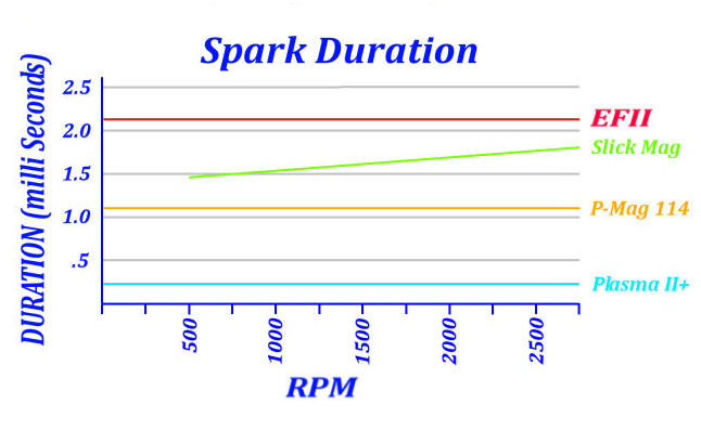
We measured the spark energy, spark duration, and system current draw of each of these systems. Below are graphs of the data that resulted. The ignitions were run under load. This means that the instrumented spark plug was mounted in a pressurized chamber of inert gas to simulate the electrical load that the spark gap sees when it is inside the combustion chamber of a running engine at high RPM and high horsepower.
System current draw at 2750 RPM: P-mag » none; Slick Mag » none; Plasma II+ » 1.5 amps; EFII » 1.2 amps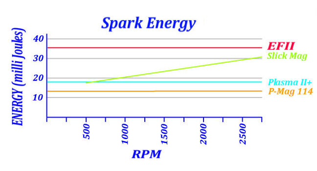
There are some interesting items in the data:
Notice the increasing energy of the magneto as RPM increases. One drawback of the magneto ignition is very low spark energy at cranking RPMs. Impulse couplings are commonly used on starting mags to momentarily speed them up in an effort to get a little more energy during cranking. This helps, but the energy is still very low during cranking.
You might expect the P-Mag to have increasing energy with RPM also, but they have chosen to limit the charge time of the coil such that the energy does not increase as rpm goes up.
Another interesting item is the very short spark duration of the Plasma II+ ignition. This is a characteristic inherent to CD ignitions. If the air fuel ratio is optimal, this may not be much of an issue. However, if you are looking for maximum power, you will be seeking an air fuel ratio on the rich side. Short spark duration ignitions will misfire before long spark duration ignitions as you continue to add fuel. If you are a lean-of-peak guy, you have a similar situation where a short spark duration ignition will start to misfire before a long duration ignition as you take away fuel. These characteristics tend to favor long spark duration ignitions for best economy as well as for best power. This is the primary reason cars all have inductive ignitions. The long spark duration of the EFII ignition means that the spark is lit for more than 36 degrees of engine rotation at 2750 RPM. This gives lots of opportunity for a non optimal mixture to light.
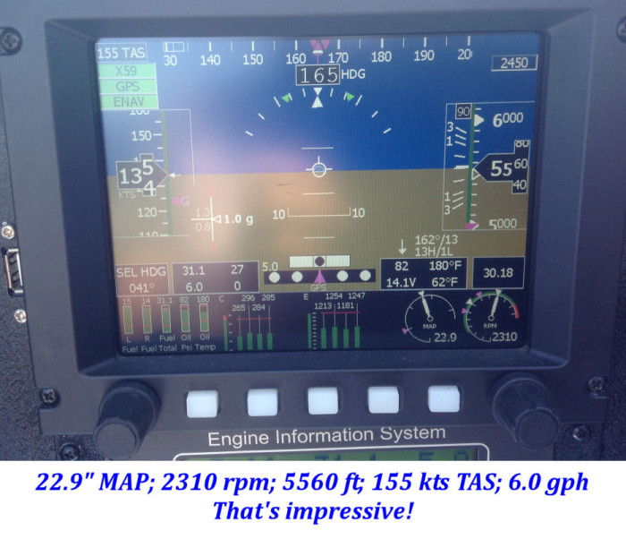
In the picture below, you can view a nice photo of Mannon Thomason's EFIS display in his RV-8. His Dual EFII ignition is helping to deliver 155 knots true at 6.0 gallons per hour - that's 178mph at 29.7 miles per gallon! - not too shabby!
 EFII Flies Above the Rest
Why does our system seem to come out on top? It's not because we're clever with our data. There are really two reasons. First, we are a technology driven company. We value function over form. Clever packaging or glossy marketing are not what we focus on. Our priorities are performance and reliability. Second, we have been designing and manufacturing performance ignitions since the 1980's. We went through our ignition design learning curves a long time ago. This allows us to design the correct product for a given application without the teething pains that others seem to go through.
The data in this article highlights only some of the differences between our system and others. Our Tefzel wire harness, OEM style connectors, and billet crank trigger are also significant in a thorough comparison. The end result of our experience and our sound design philosophy is a product with unmatched quality and performance.
This is why you too, should fly with EFII
Techie Stuff
Just in case you were wondering how to measure spark energy and duration, here is a little extra info.
It helps to have a nice oscilloscope that can do some fancy math for you. Otherwise, data can be exported to a computer for computation. Fortunately, we have an oscilloscope that is up to the task. Below, you can see a screen shot of the scope with the spark waveforms shown. This particular measurement was of the spark output of the EFII ignition.
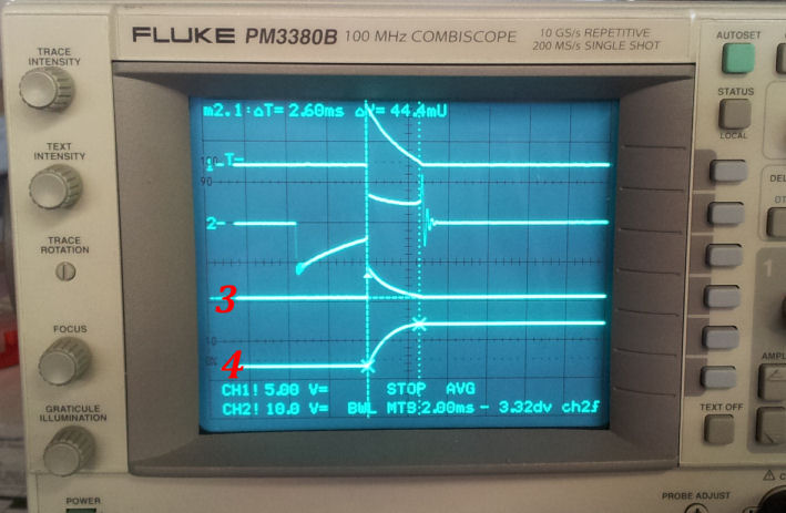
There are four traces displayed on the scope image. Trace #1 is the spark current. This measurement is made by returning the spark current through a 100 ohm resistor that serves as a current shunt. The spark current generates a signal across the shunt resistor that is a few volts in amplitude and can easily be measured by the scope. Trace #2 is the spark voltage. The voltage was measured with a 1000:1 probe. The portion of this signal that lies between the vertical cursor lines in the image shows when there is a spark present in the gap of the spark plug. Notice in trace #1, this is also the period where there is current flowing. Trace#3 is a math channel that is generated by the oscilloscope. This trace is defined as (trace#1 x trace#2) or spark current times spark voltage. Current times voltage is power. Trace #3 is a representation of the instantaneous power (in Watts) of the spark event. Trace #4 is another math channel. In this case trace #4 has been defined as the integral over time of trace #3. This can also be explained as the area under the curve of trace #3. Mathematically, this gives you the spark power (in Watts) times the spark time (in seconds) which is spark energy (in Joules). Watts times Seconds equals Joules. In this case, the energy is much less than one Joule, so we express it in milli Joules, or thousandths of a Joule. Trace #4 shows the accumulation of energy during the spark event. Notice that the #4 curve stops rising when the spark current stops. This is because there is no additional energy being delivered across the spark gap. Also notice the two small "x" marks on the #4 curve. This is an amplitude measurement function of the scope. The amplitude measured in this case is displayed at the top middle of the screen. You can see it reads 44.4 mU. The scope doesn't know what units we are actually measuring, so it has labeled the value generically as 44.4 milli Units. In this case, milli Units means milli Joules. You may notice that in this measurement, the EFII ignition is putting out 44.4 milli Joules of energy - which is a lot! The graphs above show that our ignition puts out 36 milli Joules. Spark energy readings can vary quite a bit with variations in temperature and humidity. We tried to be fair to all the systems measured and take data on the same day when we collected the info for the graphs. The scope screen shot was made on a different day with high humidity and the reading showed much higher. We want to emphasize, that we did in fact make every effort possible to evaluate all the systems fairly and under the same conditions. The data in the graphs is a result of this.
There is a little more to the energy measurement process, such as having a pressure vessel for the spark plug to fire into to simulate the load on the spark gap that is present in a running engine. There is also the requirement to trigger the different systems properly with crank trigger signals in the case of the LSE and EFII systems and to properly spin the input shafts in the case of the P-Mag and Slick Mag. We used an electronically generated crank trigger signal for the EFII system. To trigger the LSE system, we mounted a flywheel in our engine lathe and spun it with the crank trigger assembly mounted on the tool post of the lathe. The P-Mag and Slick Mag were also spun using the engine lathe. Below you can see the magneto mount rig on the lathe.
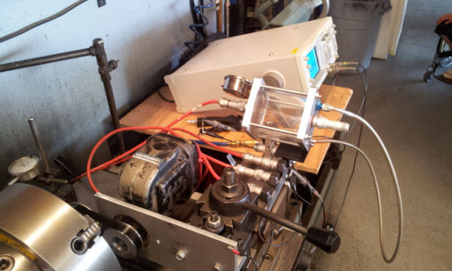 The setup shown to the right was used to test the Slick Mag and P-mag. You can see the spark pressure chamber in the image. There is an old Bendix mag in the picture. We would have added the data to the graphs from this mag, but it didn't perform very well at all. This one is overdue for overhaul. The Slick Mag we tested was brand new as was the P-Mag.
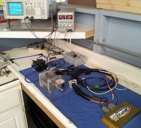 Here you can see the EFII system under test. In case you are trying to read the numbers on the power supply next to the scope, it reads 1.1 amps and 13.8 volts. This was at 2500 RPM.